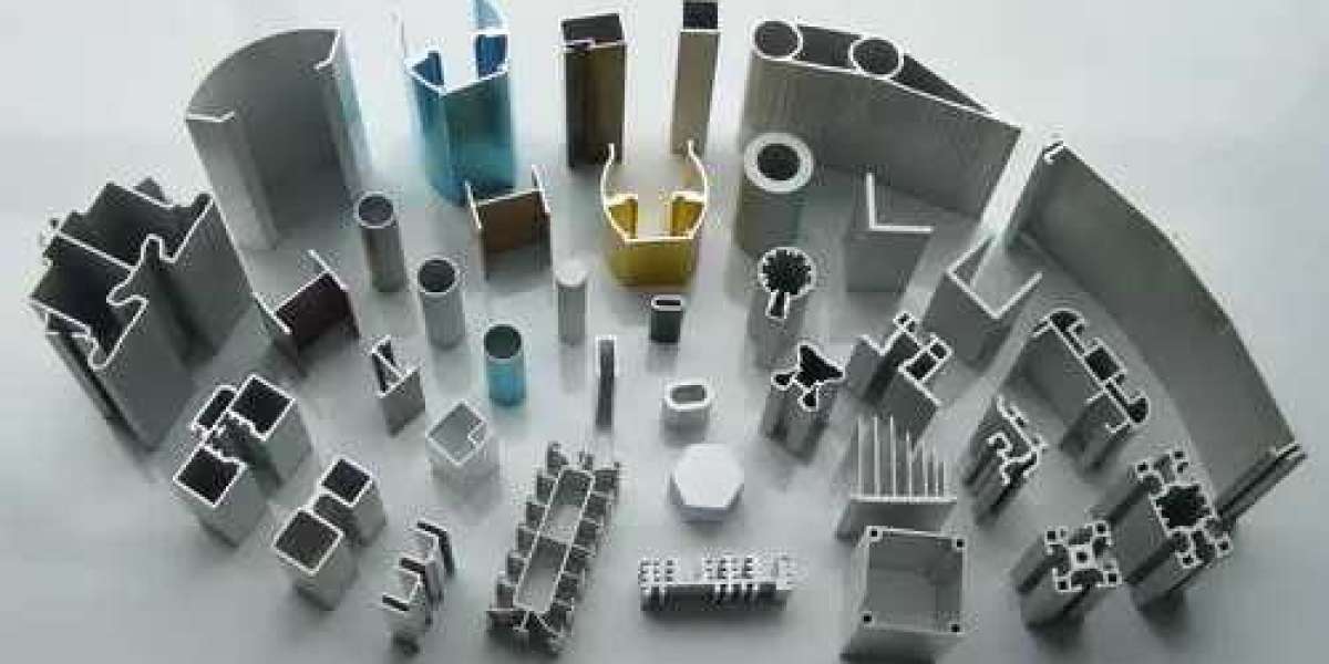
T-slot aluminum extrusions, on the other hand, make it possible to rapidly design and manufacture structural frames. However, the design of these extrusions can have a significant impact on the overall structural integrity. The following are our top three design tips for developing t-slot aluminum extrusion structures that are dependable, rigid, and suitable for industrial use. Another important factor to take into account is the cross-sectional area, which plays a role in determining the assembly's total weight. Because the most effective profiles are those that are both highly rigid and lightweight, the ratio of the area moment of inertia to the surface area is the best indicator of performance. The following table provides a list of some of the most important parameters for five different well-known extrusion models.
At this time, Vention provides a selection of six different extrusion sizes.
Our 45 mm series of extrusions are suitable for a wide variety of applications, ranging from robot range extenders to industrial furniture. There are three different sizes of extrusions that use 45 mm increments. These sizes are 45 x 45 mm, 45 x 90 mm, and 90 x 90 mm. All of these sizes share the same mounting hardware. The smallest size, 180 x 22.5 mm, is useful for applications that have low loads and low weight limits. The 45 x 45 Light-duty offers the best possible balance between the lightweight nature of the Aluminum Profile and the structural rigidity based on weight, thanks to a Aluminum Profile area reduction of 31%. This in turn results in a weight reduction of 31% per 45mm of length. The informative label "Light Duty" is a distinguishing feature of 45 x 45 extrusions that are considered light duty. Tabletop aluminum extrusion measuring 5 millimeters by 180 millimeters is an excellent choice for use as workstation table tops, CNC worksurfaces, machine-tending workstations, and morIt offers a large mounting surface that has t-slots that are evenly spaced apart, making it an excellent choice for modular jigs and fixtures.
Tabletop extrusions that adhere to the Vention standards for their t-nut profiles, v-grooves, and spacing are designed to be compatible with all gussets, assembly plates, and frame accessories. Even though it is only 5 mm thick, this extrusion is still able to support robots that produce 1800 Nm of e-stop torque. One example of such a robot is the Yaskawa HC10. That is, provided that the support extrusions are installed so that they run in a direction that is perpendicular to the tabletop. These joists should be spaced no more than 315 millimeters (distance L) apart and attached as firmly as possible to the machine's framing in order to achieve the highest possible level of strength. Add supports at regular intervals in order to increase the load capacity of the structure. Utilize the 67 in order to ensure that the tabletop extrusion is mounted flush with 45 mm extrusions. The tabletop extrusions each have a total of nine t-slots, which provides a great deal of versatility in terms of mounting options.
Perform the calculation for the safety factor.
Always ensure that you add the appropriate amount of safety factor (SF) for the circumstance. For illustration's sake, if a structure is predicted to collapse under a force of 1000 N, a safety factor of two would determine that a maximum allowable load of 500 N should be applied to it. A measure of how certain you are in the results of your calculations is referred to as the safety factor.
The following are some of the factors that should be considered when developing safety factors; however, this list is not exhaustive.
Precision and exhaustiveness in the calculation.
Conditions of the surrounding environment.
Determine the breaking strength of the material.
Buckling is an essential factor to take into account whenever one is determining the strength of a structure. Buckling is the deformation of a long vertical beam that occurs when it is compressed by a force. The beam has a propensity to bend outwards, which further compromises the structural integrity of the structure and ultimately results in a sudden failure. Because the load caused by gravity is greater than any of the other forces acting on the structure, the likelihood of this failure occurring with vertical beams is significantly higher. Determine first, based on the types of joints, which end conditions correspond to the scenario you are working with. Third, determine the safety factor by contrasting the maximum load capacity with the force that you anticipate applying based on a free body diagram.
2. The configuration of the assembly joints in a design can also make a significant difference in the rigidity and structural integrity of the design. Try not to rely on joints that are supported by friction to carry the load. The strength of the structure is increased due to the fact that force is transferred directly from the horizontal to the vertical extrusion. Friction joint: This type of joint is not recommended. Reduced strength; force transmission occurs via friction between the plate and the extrusion.
High tensile strength; force is transmitted directly to the frame through contact with vertical extrusions. Joint is reaction force-based, which is the recommended design. When it is impossible to avoid using friction-only joints, the joint's strength is determined by the number of fasteners that were used multiplied by the friction force that was applied by each fastener. Each M8 Vention fastener, which is the type that is used in extrusions, has the capacity to withstand 2100 N of friction.
In the previous illustration of a friction joint, each individual fastener has the potential to generate 2,100 N of friction when it is tightened to 13 Nm. As a result, the horizontal beam has the capacity to support a maximum load of 12,600 N (that is, 2,100 N multiplied by the number of fasteners, which is six).
One of the most effective ways to reduce expenses while increasing the quality of your design is to calculate the required size of the assembly plate. Simply switching out assembly plates that have six, seven, or eight fasteners for ones that have fewer fasteners enables our application engineers to routinely cut costs by as much as fifteen percent. Because these three distinct extrusions are joined together in this configuration (that is, one extrusion is vertical and two are horizontal), none of the plates are dependent on friction alone.
Extrusion systems of a high strength should be used for applications of a demanding nature.
The structural integrity of your assemblies can be improved by combining effective assembly joints with the appropriate extrusion profile. High-precision assembly plates manufactured by Vention (part numbers ST-HP-XXX-XXXX) feature a patented V-shaped boss (protrusion) on the plate underside. These plates are ideal for use in heavy-duty or precise applications. Enhances the resistance to slipping by transforming friction-bonded joints into structurally bonded joints. Your decision is determined by whether you want to maximize your efficiency (GP) by decreasing costs or increasing your power and precision (HP).