The subsequent machining process is made more difficult because these components are frequently lightweight and have complex geometries. This contributes to the difficulty of the process. Nevertheless, we have no choice but to carry out these steps. In this issue, the editor will be discussing with you the challenges and solutions in the machining of 3D printed parts through a case of machining of 3D printed metal parts that has been shared by additive manufacturing experts. This discussion will be based on a case of machining of 3D printed metal parts that has been shared by additive manufacturing experts. The machining of metal parts that were 3D printed will serve as the basis for China die casting mold this discussion, which will be based on a case that was shared by additive manufacturing experts. However, when one takes into account the difficulties that may arise during subsequent machining, the benefits that can be gained from additive manufacturing technology are sometimes diminished. This is because of the fact that additive manufacturing technology relies on subtractive manufacturing technology. This is due to the fact that the technology of subtractive manufacturing is necessary for the technology of additive manufacturing to function. This is because the technology of subtractive manufacturing is required for the technology of additive manufacturing in order for it to function properly. The failure of an additively manufactured part can result in financial losses, which can be avoided by taking into adequate consideration the difficulties of subsequent machining during the initial stages of the part's design and production process.
Machining is typically required to be performed on components that have been printed using a 3D printer before they can be assembled with other components. This is the case even if the components were printed in the same location as the other components. Even if the components were printed in the same location as the other components, this result will still be obtained. In addition, the complex structure makes it more difficult to clamp the workpiece in place in such a way that it is secure because it presents a greater number of challenges. Is there a possibility that the component will become dislodged from the tool and begin to vibrate, which will then cause the tool to vibrate, which will result in machining that is below standard. The use of a scanning electron microscope as the instrument of analysis is the most appropriate course of action to take in order to achieve this goal. It is absolutely necessary to achieve a 5-axis alignment of the component that is as precise as it is possible for a human to achieve. This is accomplished by performing a variety of diagnostic procedures on the product. To put it another way, the peak force is roughly twice Plating as high as the value that is considered to be typical. The fact that the simulation was actually carried out allowed for the successful completion of this investigation. In addition, the results of the finite element analysis showed that there was a significant amount of distortion. This distortion, if it is not fixed, could lead to uneven cutting if it is not addressed.

At the outset, there is a requirement for an initial trial run with the cutting.
If it is carried out under the conditions that have been described in the previous paragraphs, machining will lead to problems such as part deviation from the tool and rebound, surface vibration, and tool vibration. These issues will all occur simultaneously.The surface finish that is produced as a direct consequence of these issues is of a quality that is lower than that which is considered to be the standard within the industry.Both of these components are essential in order to achieve the desired outcome with the project.
One of the goals of the modification process should be to increase the rigidity of the component so that it can be printed using 3D printing. This should be done when modifying the design of a component so that it can be printed using 3D printing.It is imperative that this particular point be brought up because of the significance it carries.
In this particular case, the specific solution for the re-clamping method is to design a customized fixture for the 3D printing part, and then use the 3D printing equipment to directly manufacture the customized fixture. This is the solution for the specific problem that has arisen.This is the answer to the particular issue that we have been struggling with recently.This not only decreases the likelihood of the part becoming misshapen or the surface becoming damaged, but it also causes the 3D printed parts to move closer to the features that were machined, which in turn reduces the amount of deflection and vibration that the part is subjected to.
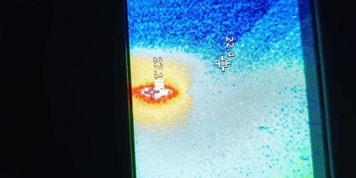
The designers found out while conducting a finite element analysis of the 3D printed part while it was mounted in a fixture that the stiffness of the part could be improved even further by better clamping the straight structures that were already contained within the part. This discovery was made while the part was in the process of being mounted in the fixture.This image shows a topology-optimized three-dimensionally printed part being measured on a flex gauge in order to generate a five-axis alignment for subsequent processing. The alignment will be used for the manufacturing of the part.This is where the image was displayed.To ensure that there are no mistakes made during the manufacturing process, these tolerances are essential.To ensure that there are no errors made during the process of manufacturing, it is essential to have these tolerances in place.However, because the precision datum needed to be added to the final machining operation after all of the other surfaces had been generated, this process was not carried out in the typical manner for the part that was 3D printed in this instance. Instead, the precision datum was added after all of the other surfaces had been generated.In its place, the precision datum was brought in after the generation of each of the model's other surfaces.The probing and metrology software can still be used at this stage of the production process to determine the settings that will produce the best results when it comes to the finishing process. This step of the process takes place after production is complete.